Accelerometer
What is an accelerometer?
An accelerometer is an electromechanical device that will measure acceleration forces. These forces may be static, like the constant force of gravity pulling at your feet, or they could be dynamic – caused by changes of the speed and the direction of the movement (acceleration – deceleration, turns).
Where is it used?
It is used mainly on Navigation or Guidance Systems called Inertial Navigation System (INS), or Inertial Reference System (IRS), or Inertial Reference Unit (IRU) or Air Data Inertial Reference Unit (ADIRU). These systems use Accelerometers Gyroscopes and electronic circuitry to provide accurate Guidance, Navigation, Position calculation, Speed measurement and Attitude determination, factors absolutely necessary for the auto pilot operation on sea and air vehicles. On airplanes the Flight Data Recorder use Accelerometers to measure and record acceleration forces on the three axis of the vehicle, and on cars the accelerometers are used to deploy the air bags at the right time.
How do accelerometers work?
An accelerometer usually uses a concentrated mass (seismic mass), which resists movement because of its inertia. The displacement of the seismic mass relative to its supporting frame or container is used as a measure of acceleration.
There are many different ways to make an accelerometer. Some accelerometers use the piezoelectric effect – they contain microscopic crystal structures that get stressed by accelerative forces, which cause a voltage to be generated. Another way to do it is by sensing changes in capacitance. If you have two microstructures next to each other, they have a certain capacitance between them. If an accelerative force moves one of the structures, then the capacitance will change. Add some circuitry to convert from capacitance to voltage, and you will get an accelerometer. There are even more methods, including use of the piezoresistive effect, hot air bubbles, and light.
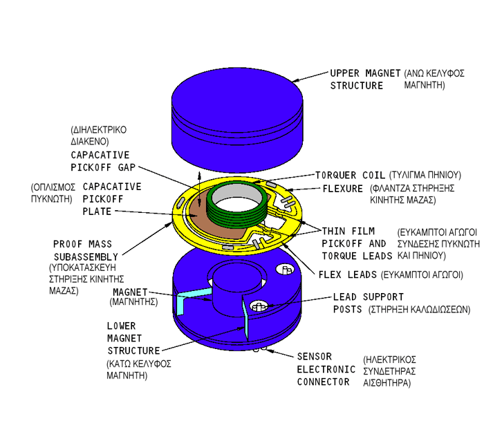
Here we are going to describe the operation of an accelerometer using the capacitance effect, which is part of an Inertial Navigation System or Inertial Reference Unit (IRS) used on passenger airplanes.
Looking at the schematic diagram above, we can see the proof mass in orange colour placed between the magnets. Around the proof mass there is a torquer coil.The suspension metal blade of the proof mass in yellow colour, comprise together with two plates above and below it, two capacitors of the same value when the proof mass is null.
Acceleration along the input axis moves the proof mass. Capacitive pickoff converts the position change into an electrical error signal to the servo amplifier. The servo amplifier nulls out the error signal by returning the proof mass to the zero-position using the torquer coil. The current in the torquer coil needed to null the error signal is the analog output signal representing acceleration. The analog output signal is integrated once to give velocity and integrated a second time to give distance.
Reference : Boeing Aircraft Maintenance Manuals


